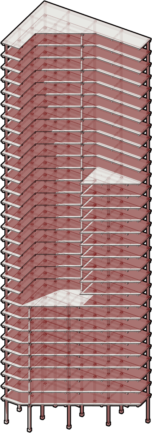
Timber Office Carbon Tool.
- Type./
- Parametric design research
- Date./
- 2026, in progress
- Scope./
- Timber offices, England
- Tools./
- Rhino 8, Grasshopper, Karamba
- Context./
- RIBA 2030 Climate Challenge
A Grasshopper definition that generates a timber office structure and the quantities behind its carbon. The browser model on this page lets anyone try a footprint and see what changes.
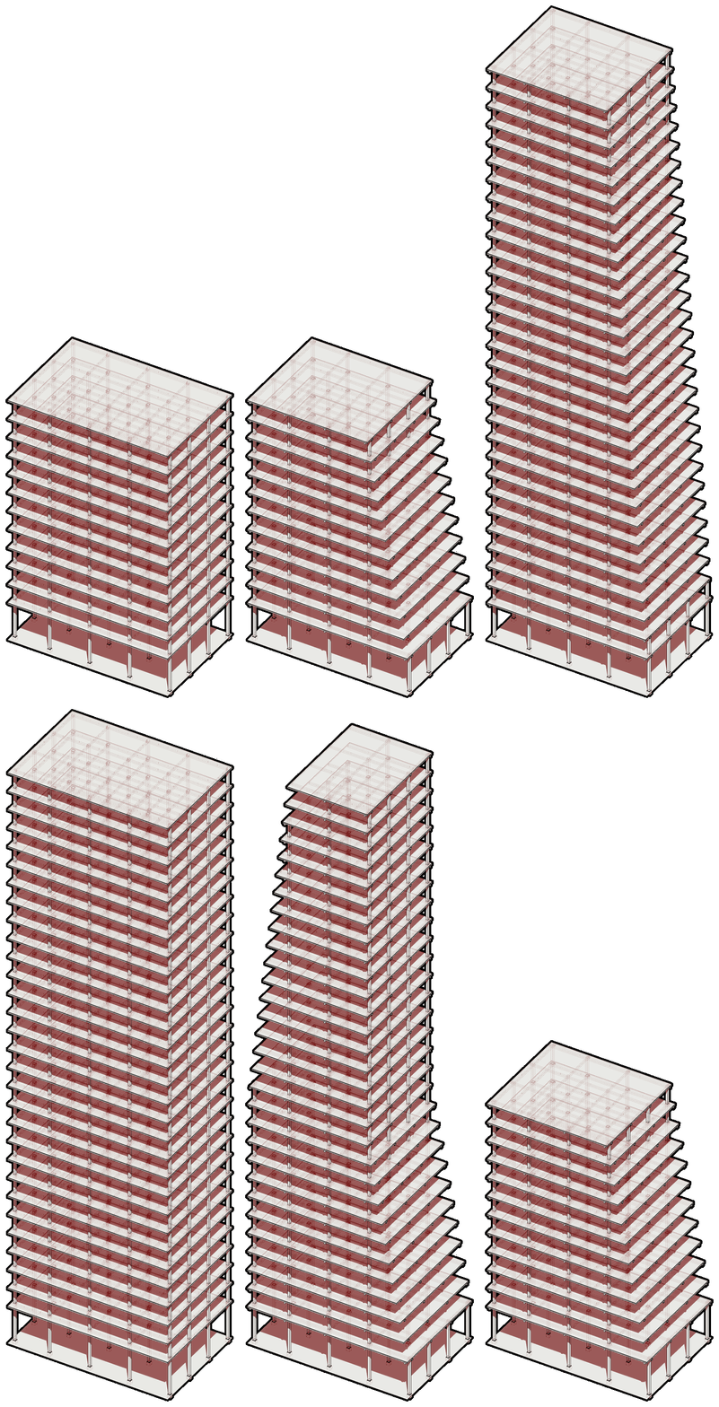
Change the inputs, the structure rebuilds.
Each frame is the same Grasshopper definition with different inputs. Change the footprint, storeys or grid and the timber structure regenerates with its quantities.
- Footprint./A rectangle or a custom boundary curve sets the floor plate; inner trims become cut-outs.
- Grid./Target spacings in X and Y are equalised across the plate to place glulam columns and beams.
- Storeys./Storey count, floor-to-floor height and an optional double-height lobby stack the CLT floor panels.
- Quantities./Panel, beam and column volumes feed the carbon ledger further down this page.
Indicative geometry for exploring options. No structural analysis has been run yet.
Try a footprint and see what changes.
Work through the five steps on the left. Every change updates the drawing, the 3D model and the carbon totals at once. Click any part of the 3D model to see where its carbon comes from and what would save the most.
Material figures come from ÖKOBAUDAT, the German government’s open building materials database, and product EPDs. The structure follows FCBStudios’ FCBS CARBON tool, credited with thanks. See the method and every source.
Draw the footprint and set the height. The plan on the right updates as you go: drag its corners when using a custom outline.
- Move drag a corner. Corners also line up with each other.
- Add drag from the middle of an edge.
- Remove double-click a corner, or select it and press Delete.
- Redraw press Draw new outline above the plan, then click to place corners.
Edit exact coordinates
Stays in sync with the plan. The outline closes itself; keep it to a simple shape with no crossing edges.
Replaces the first typical interval, removes the intermediate floor at the original level and raises the building top by the difference.
Choose the frame and how it is sized. Glulam beams and columns are checked automatically for each grid.
Quantity scenario only. 160 mm is an illustrative geometric input, not a selected or checked floor panel.
Centred core, area subtraction only. It does not clip grid nodes or model stability walls or openings.
Timber member sizing and loads
Single-span beams along X between columns, carrying a strip of floor equal to the Y bay. Auto searches HASSLACHER’s 80–280 mm widths and 40 mm height steps for the smallest section that passes bending, shear and final deflection (span/250).
CLT self-weight is added automatically. 3.3 kN/m² = 2.5 office imposed + 0.8 movable partitions; confirm both with the engineer.
Pinned columns at every grid node, checked for buckling under the floors above. Upper storeys get smaller sections. Auto goes up to 280 mm wide, then to block-glued squares up to 560 mm, which HASSLACHER makes by bonding blocks together. Fire, connections and edge loading are not checked.
An assumed uplift on the timber figure for steel brackets, screws and plates. Not sourced: replace it with a connection take-off.
Pick the façade, windows and roof. Glazing ratio changes both embodied carbon and the light study.
Fit-out is replaced several times over 60 years, so it often matters more than it looks.
How the building runs over 60 years, plus transport and cost assumptions.
RIBA 2030 asks offices for 55 kWh/m²/yr or less by 2030 and 110 by 2025; a typical existing office uses about 225. The decarbonising grid option is illustrative: today’s factor falling to 0.02 kg CO₂e/kWh by 2035.
Default is a rough road distance from HASSLACHER in Austria to central England. Both distances use the CLT EPD truck factor.
Floor uses and load categories
Candidate actions at right are unverified transcriptions; compare with the licensed UK National Annex and obtain engineer confirmation before design.
Total floor-area share:
Loading 3D view…
Loading 3D view…
● interior grid node · ○ perimeter node · ▧ optional core
| Façade facing | Glazing | Direct sun, this day | Year average |
|---|
Façades are coloured by hours of direct sun on the chosen day: pale is little or none, deep amber is the most. Sun hours count the time the sun is above the horizon and in front of each façade. They don't include shading by the building itself or by neighbours; the shadows in the 3D view show that. Times are solar time (12:00 is when the sun is due south); add an hour in British Summer Time.
Build it up, layer by layer.
Where the carbon sits, part by part. Open a group to see each element’s upfront and 60-year carbon; click one to inspect it in the model above.
How quantities are worked out
Node preview rule: grid nodes are counted when their point lies inside or on the outline. A node near an irregular edge is not proof of a feasible column, edge beam or load path. Grid clipping and structural framing need engineer-led detailing.
Read it as drawings.
Plans of every level, two sections and a wall section, drawn live from the model above. Each build-up is drawn layer by layer at its real thickness, with its upfront carbon per square metre.
Line weights follow the usual hierarchy: what is cut is heaviest, what is seen beyond is lighter, and grids and dimensions are finest. Each sheet downloads as an A3 drawing at true scale.
The drawings appear when you scroll here.
Drag to move around · Ctrl + scroll or pinch to zoom · double-click to fit. Indicative only, not for construction.
Sixty years, one building.
See where the carbon goes over the building’s life, which parts matter most, and how it compares with UK benchmarks. Take the full schedule away as an Excel workbook, or open the model in Rhino or Revit with every element carrying its material and carbon data.
The workbook keeps live formulas, and you can import it back here to restore the project. The Rhino file has one layer per part, and each object stores its material and carbon as Attribute User Text. The Revit model is an IFC4 file: in Revit choose File › Open › IFC and save it as an .rvt. It arrives with levels, walls, floors, roofs, columns, beams, windows and foundations in their Revit categories, layered materials, and a CarbonTool parameter set you can schedule. The elements come in as fixed shapes rather than editable system families, as with any IFC from outside Revit.
Steps show replacements at each part’s RICS lifespan. Stored carbon is counted when the timber is installed and released at end of life (year 60).
Find the lighter frame.
The chart reruns the whole model for every grid spacing from 3 to 12 m, changing one direction at a time and keeping everything else as set above. It shows where wider bays start costing more carbon in deeper beams and heavier columns.
Save up to three options to compare them side by side. Each saved option has its own share link.
Show as table
| Spacing (m) | X changed, kg CO₂e/m² | Y changed, kg CO₂e/m² |
|---|
Saved in this browser only. Use each option’s link to share it.
Count the whole timber frame, and show its boundary.
The geometry above now sets three quantities: CLT slabs, glulam primary beams and glulam columns. CLT uses the Stora Enso EPD. Glulam uses the HASSLACHER EPD, the manufacturer behind the James Jones glulam range. Beams and columns are sized by simple Eurocode 5 preliminary checks using HASSLACHER’s strength data, and connections are added as a stated allowance.
Each figure is A1–A5 upfront carbon with stored biogenic carbon kept out, as SCORS and RICS require. It is a frame-only estimate, not a full project result.
Boundary: CLT slabs, glulam primary beams and columns, plus a connection allowance. Foundations, the core, stairs, secondary beams, façade, fit-out, full A5 site works and waste are not included. The SCORS position is frame only. Do not compare it with RIBA 2030 or LETI targets, which cover the whole building. Read the full method.
These are preliminary EN 1995-1-1 checks with UK National Annex values: kmod 0.8, γM 1.25, kcr 0.67, kdef 0.6, ψ2 0.3, final deflection span/250, and ULS 1.35g + 1.5q. Strength and stiffness come from HASSLACHER’s technical manual. Where a section falls within HASSLACHER’s GL24h pre-design table (up to 360 mm deep), its tabulated span is shown as a cross-check. Edge beams and columns carry less load but are sized the same, which is conservative. These checks are not a structural design and need an engineer’s confirmation.
| Module | GWP-total kg CO₂e | GWP-biogenic kg CO₂e |
|---|
Stora Enso CLT, 2024 EPD. A1–A3 GWP-total is −708, including −762 kg biogenic storage, so the fossil and other part used here is 54 kg. A4 scales the EPD’s 634 km truck scenario. A5 covers packaging and lifting only.
| Module | GWP-total | GWP-fossil | GWP-biogenic |
|---|---|---|---|
| A1–A3 | −608 | 144 | −753 |
| A4 / A5 | Not declared in this EPD | ||
| C2 | 1.42 | 1.41 | 0.00 |
| C3 | 753 | 3.74 | 750 |
| D | −410 | −408 | −1.42 |
HASSLACHER glued laminated timber, EPD-HAS-20210171-IBD1 (IBU), 1 m³ at 470 kg/m³, valid until 02.08.2026, so it has now expired. Cross-checks: the current Studiengemeinschaft Holzleimbau industry EPD (EPD-SHL-20240270-IBO1, valid to 2030) gives 143.5 kg fossil A1–A3, and IStructE’s generic glulam factor of 0.28 kg/kg gives about 132 kg/m³. A5 uses the SHL EPD’s 4.01 kg/m³. Replace these when HASSLACHER publishes a renewed EPD.
Design the building. Understand the impact.
For everyone: explore the footprint, grid and material choices behind a timber office. For the technical team: Rhino and Grasshopper are the editable project model, where geometry, quantities, source data and future structural checks belong.
- Grasshopper is the technical source
- Structural scope first
- Example: 30 × 24 m
- RIBA 2030 context
The GH definition generates separate CLT panel solids, adjustable glulam beam and column solids, and adjustable L-core wall placeholders. Footprint, storey, grid, member section, CLT thickness and panel module sliders drive the geometry. In custom-boundary mode, a closed curve or one horizontal planar trimmed Brep can define the footprint; inner Brep trims are treated as floor cut-outs. The model clips floor panels and grid framing to that outline, and adds perimeter beams and column supports at an adjustable offset.
The browser sandbox below demonstrates simple polygon outlines only, and neither workflow confirms structural feasibility. Joint markers are review zones, not connection hardware. Stair, lift-shaft and service-riser zones are marked relative to the L-core but do not cut slab openings. The gravity-load path and L-core stability role are conceptual and unverified. Karamba currently receives a beam-column line model with its default steel section; timber properties, shell/diaphragm elements, verified loads and supports are still outstanding, so no structural analysis has been run.
What is built, and what remains open.
The project has moved from concept geometry to a developed-design work package. Phase 3 has started but is not complete: project-specific analysis, complete carbon scope and engineer review remain open.
- Phase 0 · specification
Brief and data structure
UK-wide applicability, structural scope first, RIBA 2030 context. ICE factors remain unpopulated until sourced.
- Phase 1 · concept
Grid and basic quantities
The earlier Rhino/GH definition has a rectangular footprint, grid and columns. This page adds an exploratory irregular-footprint calculation.
- Phase 2 · options
Grid and option comparison
The browser tool now sweeps grid spacing from 3 to 12 m in each direction and compares up to three saved options. Multi-variable optimisation and repeatable baselines come next.
- Phase 3 · in progress
Developed design
Glulam beams and columns now get preliminary EN 1995 checks (bending, shear, deflection, buckling), using HASSLACHER properties. CLT panel checks, fire and connections are still to come, and no engineer has reviewed the method yet.
- Review gate
Engineer confirmation deferred
Candidate floor-use actions are not verified against a licensed controlled standard or approved for this project.
- Whole-building scope
Not included yet
Façade, fit-out, MEP, foundations, operational energy and whole-building RIBA comparison are outside this structural companion.
Illustrative areas and candidate actions.
Area shares are editable and kept at a 100% total by scaling the entered shares. Category choices only select candidate characteristic actions; blank or conditional entries do not become a design load.
| Use / category | qk kN/m² | Qk kN | Status |
|---|
Not a loading model. These characteristic imposed actions are not combined with self-weight, finishes, partitions, plant, snow, wind, fire or construction actions. No load reductions or ULS/SLS combinations are applied. Values need controlled-copy verification and engineer classification.
Preliminary checks now, product design next.
Glulam beams and columns are sized in the browser by simple Eurocode 5 checks so that their carbon can be counted. These are comparison checks for concept stage, not a design. Product-specific tables and an analytical model (Karamba3D) follow for developed design. See the sizing method.
- CLT
Panel selection
Needs product-specific layup and stiffness, support continuity, span, permanent and imposed actions, openings, bending, shear, rolling shear, bearing, deflection/creep and vibration.
- Glulam beams · preliminary
Floor beam selection
Done at concept level: tributary width, line load, grade, bending, shear and final deflection. Still open: lateral stability, bearing, vibration, fire and notches.
- Glulam columns · preliminary
Axial buckling
Done at concept level: accumulated axial load and flexural buckling per storey. Still open: moment from eccentricity, biaxial interaction, restraints, fire and connections.
Rule for product tables: when manufacturer tables replace the preliminary checks, each lookup must match the product, revision and input range exactly and show its governing check. Outside the table range the tool must say NO MATCH — ENGINEER CALCULATION REQUIRED and never extrapolate.
Open engineering work.
The tool can recalculate quantities and present candidate source data. It cannot approve a structural solution, set a fire strategy or replace professional design.
- Choose one coherent Eurocode generation with the project engineer. BSI states first-generation UK Eurocodes remain applicable until 30 March 2028 unless the authority or specification differs; recheck transition status.
- BS EN 1990 and UK NA: basis, ULS/SLS combinations and serviceability criteria.
- BS EN 1991-1-1 and UK NA: §§5.1–5.2, 6.1, 6.3.1.1–6.3.1.2, 6.3.2.1–6.3.2.2, 6.4; UK NA Tables NA.2–NA.5 and NA.8 as relevant.
- BS EN 1995-1-1 and current UK NA: §§2.3, 3–5, 6.1, 6.3, 7.2, 7.3 and 8; check product properties, service class and duration.
- Also assess wind, snow, execution, accidental actions, fire, geotechnical, concrete/steel and composite standards as the scheme needs.
Clauses are navigation aids, not a substitute for controlled copies of the exact licensed edition and UK National Annex.
- CLT: bending, shear, rolling shear, bearing, openings, joints, deflection/creep, vibration and fire.
- Glulam beams: bending, shear, bearing, lateral stability, notches/holes, deflection, vibration and fire.
- Columns: compression, biaxial bending, buckling, restraint, imperfections and connections.
- Stability core, diaphragms, connections and fixings, robustness, foundations, ground conditions and construction sequence.
- Fire strategy: structural fire resistance, encapsulation, cavities, external walls, escape and firefighting provisions, sprinklers where relevant.
England: use current Building Regulations and Approved Document B for the building's height and use. Higher-risk building controls may apply by statutory criteria. Height thresholds do not by themselves certify a timber system; obtain project fire and structural engineering input.
Compare product evidence before selection.
A supplier shortlist is not procurement approval. Confirm UK availability, product approval, declarations, design properties and project-specific support with the supplier and engineer.
- CLT · first EPD example
Stora Enso CLT
Selected only to illustrate a published product EPD. Confirm UK supply route, configuration, current declaration and delivery scenario.
- CLT · alternative
KLH UK technical data
Request a comparable product-specific EPD, layup, strength and stiffness data and current design tables.
- Glulam · UK supply
James Jones glulam
Confirm grade, declaration and distribution route; compare alternatives on the same design and carbon basis.
Sources.
Links are provided for checking. Product EPD values are source-derived, but the project-specific application, source edition and quantities remain to be verified.
- HASSLACHER glulam EPD (EPD-HAS-20210171-IBD1) · glulam factors; expired 08/2026, renewal to check.
- Studiengemeinschaft Holzleimbau glulam EPD (EPD-SHL-20240270-IBO1) · glulam A5 and cross-check.
- IStructE SCORS introduction · rating bands and scope.
- Tool method · every assumption and factor in one place.
- BSI Eurocodes transition · standards-generation status; recheck current date.
- BSI UK NA to EN 1991-1-1 · controlled first-generation NA catalogue.
- BSI BS EN 1995-1-1 and current UK NA.
- Public transcription of UK NA table entries · candidate values only; not a controlled standard.
- RICS Whole Life Carbon Assessment, 2nd edition · methodology and reporting basis.
- RIBA 2030 Climate Challenge and v2 guidance PDF · full-building context.
- Stora Enso CLT EPD record and EPD PDF · declared unit and module factors above.
- Swedish Wood CLT Handbook (UK Edition) · design context, not a replacement for selected product design.
- Glulam Handbook Vol. 1 (2024) · roof tables only apply to stated assumptions.
- Approved Document B, England and higher-risk buildings guidance.
- BS ISO 24323:2023 · timber floor vibration method; check scope.
Illustrative calculations for exploration and discussion. No design values are approved by a structural or fire engineer. Values on this page update in your browser only and are not written back to the Grasshopper file. Last content update: 27 October 2026.